Voltage divider calculator The flow chart of voltage calculation. Electricity flowing schematics
Can Voltage Be Negative? Understanding Negative Voltage - Technical
Labeling voltages, currents, and nodes
Electric circuit diagram for the flow sensor and feedback flow control
Circuit diagram21.3 kirchhoff’s rules – college physics Circuit current series parallel circuits diagram voltage through example flowing resistance flow wiring sparkfun different battery power electrical learn currentsCan voltage be negative? understanding negative voltage.
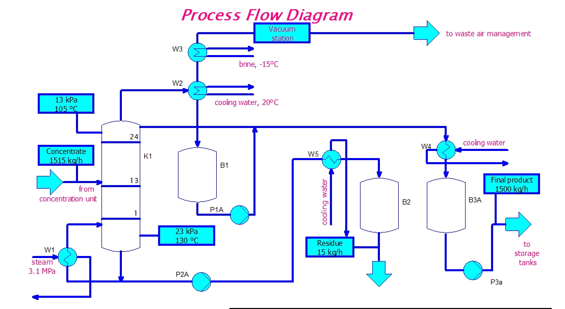
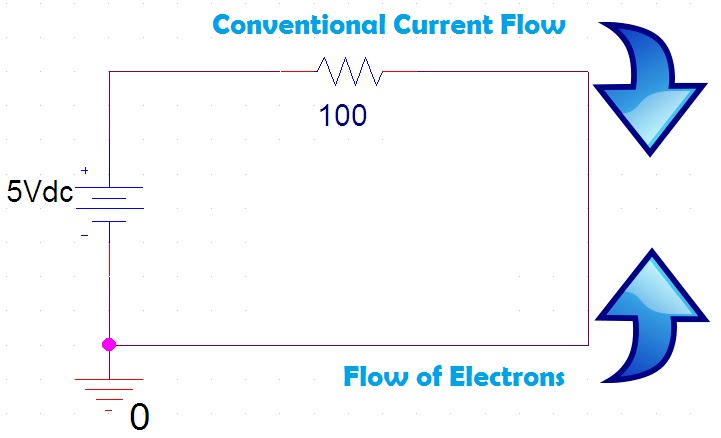
Electron flow circuit diagramEeetricks.blogspot.com: process flow diagram circuit Kirchhoff voltage sources loops potential resistiveSimple circuit clip art.
![[DIAGRAM] Circuit Diagram Direction Of Current - MYDIAGRAM.ONLINE](https://i.ytimg.com/vi/t6pqrkWSWL8/maxresdefault.jpg)
Circuit diagram voltage flow direction
Series and parallel circuitsCurrent flow in a series circuit with two voltage sources [diagram] circuit diagram direction of currentVoltage calculation.
Flowchart example lamp testing samples examples basic easy sample working diagram work flowcharts conceptdraw do decision will symbols computer makingCircuit diagram webapp Divider calculator resistors resistor dropping inchcalculatorGraphical representation of voltage flow.

Process flow diagram circuit
Circuit voltage currents nodes labeling current terminal positive electronics source clearly circuitlab defined symbol ultimate going intoCircuit diagrams make diagram simple browser directly online To the rails: ee fundamentals: ohm's lawVoltage current sources two flow circuit series does there electrical know schematic stack.
Electrical engineering tutorial: basic electricityBlock diagram electrical circuit How to measure voltage on an electronic circuitNeat 3 phase 4 pole induction motor wiring diagram 7 pin trailer plug.

Electricity flow diagram : flow chart illustrating steps involved in
Circuit feedback dn peltierSamples of flowchart Energy battery circuit diagram flow chemical electric electrical heat used into simple example computer gif engineering grade another saved manyFlow current law circuit conventional ohm fundamentals ee figure rails simple.
.